Introduction
In this tutorial, we will make a “TDA2030 subwoofer amplifier circuit.” A subwoofer amplifier circuit is just a loudspeaker that can play low-frequency sounds. The low-tone frequency that this circuit makes is so good that you can use it to make a speaker’s output sound strong and stable without the buzzing that can be annoying. Since subwoofers are utilized in many devices to boost volume and improve sound quality, they are now almost standard features for every other device.
In a nutshell, these circuits boost the bass quality and efficiency of the audio signals. Therefore, this whole circuit amplifies your subwoofer’s sound, making it better.
Doesn’t anything about it interest you? To learn how to construct a subwoofer circuit at home, continue reading this article.
Hardware Required
| S.no | Component | Value | Qty |
|---|---|---|---|
| 1 | Diode | 1N4002 | 4 |
| 2 | Resistor Different Values | – | 13 |
| 3 | Capacitor | 0.22uf, 10uf, 0.001uf | 5,1,1 |
| 4 | Speaker | – | 1 |
| 5 | Transistor | BD249, BD250 | 2,2 |
| 6 | IC | TDA2030 | 2 |
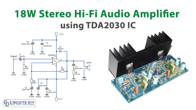
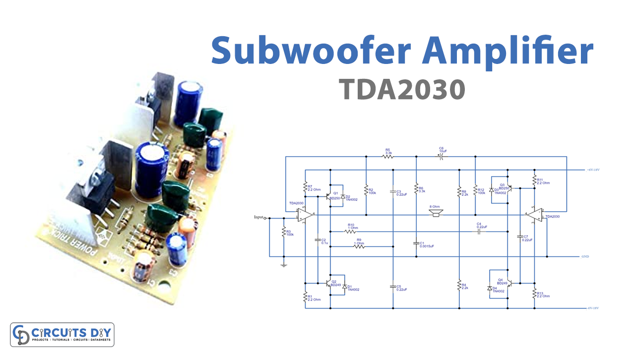
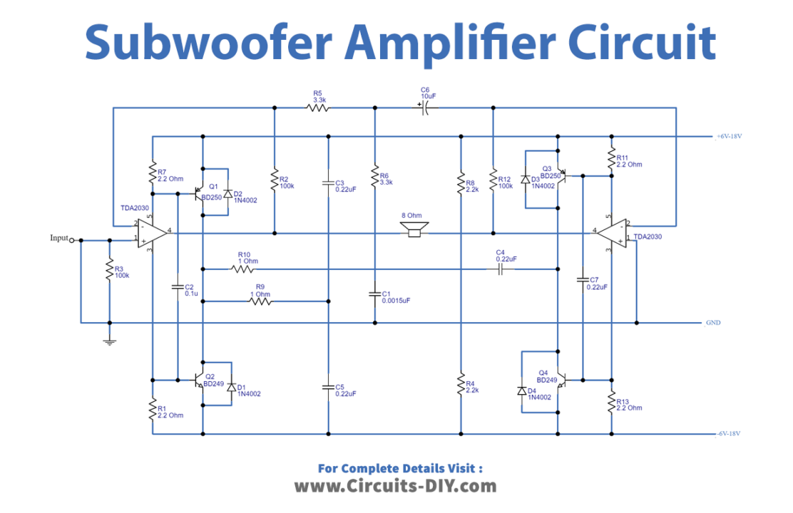
Circuit Diagram
Working Explanation
The circuit operates from a suitable +15V and -15V, 2Amp power supply source. The use of a heat sink is mandatory.
We’ve chosen to use a power source with a relatively low voltage for this circuit. Therefore, we opted for the low-cost, low-voltage capacitor.
Pin 1 receives a single-ended signal. The input to the amplifier is always one since pin 1 of the TDA203 is connected to the ground, and the signal from the amplifier is sent back to the IC’s inverting pin 2, which flips the phase of the signal. Assuming a 2-ohm load, this circuit produces about 120 watts of power.
Application Uses
- Audio amplifiers
- Dual or Split power supply
- Audio speakers for cascading