Introduction
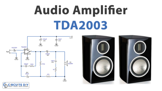
A microphone and speaker are necessary devices used at public speaking engagements and theatrical plays since they are an essential feature of any public event. We utilize mics to magnify human sounds at some gatherings, while speakers simply play music from any music player or cell phone at others. We built amplifiers into the systems, which boost audio signals from any device. In other words, amplifiers amplify low-power input electronic audio signals at the output. So, in this tutorial, we will see How To make an Audio Amplifier Circuit using TDA2030 IC.
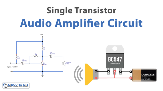
The TDA2030 is a monolithic integrated circuit. This IC provides 14W of output power and can be used as a low-frequency amplifier. This IC has a high output current, minimal harmonic distortion, and low crossover distortion. Also, it includes a short-circuit and very high-temperature protection mechanism.
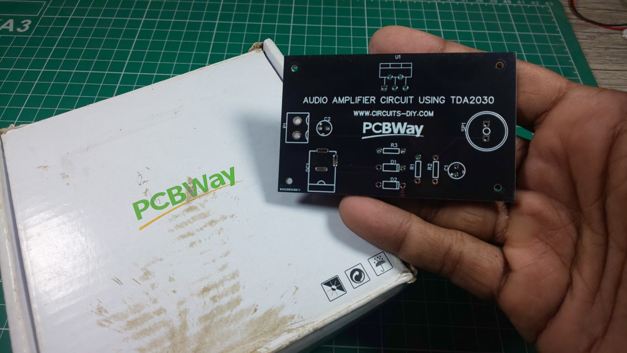
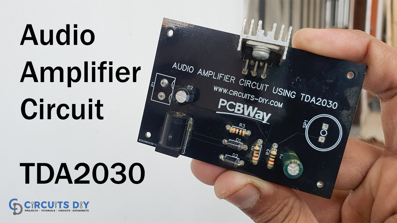
PCBWay commits to meeting the needs of its customers from different industries in terms of quality, delivery, cost-effectiveness, and any other demanding requests. As one of the most experienced PCB manufacturers in China. They pride themselves to be your best business partners as well as good friends in every aspect of your PCB needs.
Hardware Components
The following components are required to make Audio Amplifier Circuit
| S.no | Component | Value | Qty |
|---|---|---|---|
| 1. | IC | TDA2030 | |
| 2. | Heatsink | – | 1 |
| 3. | loudspeaker | 1W | 1 |
| 4. | DC Audio Jack | Female/Male 3.5mm | 1 |
| 5. | Diode | 1N4007 | 2 |
| 6. | Capacitor | 100uf, 47uf | 1, 1 |
| 7. | Resistor | 1K | 3 |
| 8. | DC Power Jack | 12V | 1 |
| 9. | DC Battery | 12V | 1 |
TDA2030 Pinout
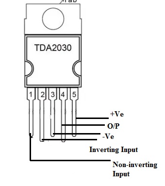
For a detailed description of pinout, dimension features, and specifications download the datasheet of TDA2030
Audio Amplifier Circuit
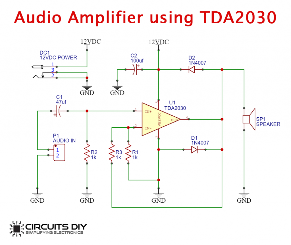
Working Explanation
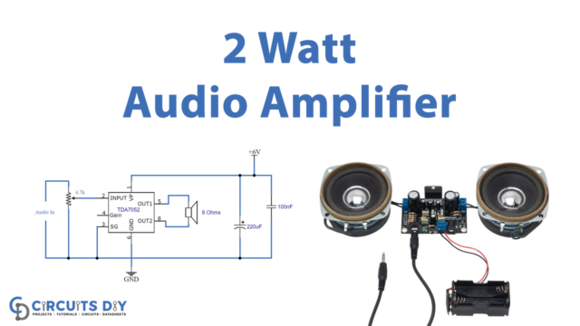
The operation of this Audio Amplifier Circuit using TDA2030 IC is actually quite simple. First, we are providing a 12V DC supply. You can use 6V to operate this circuit an audio input device, such as a smartphone or a microphone, is used. It then passed the audio input through a 47uF coupling capacitor.
The circuit is effectively blocking the DC component of the input signal using a coupling capacitor, letting only AC pass through. We then wired the capacitor output to the IC’s non-inverting input pin.
The amplifier’s amplified output is subsequently delivered to an audio transducer like a loudspeaker. We use two flyback diodes to prevent the amplifier from negative feedback.
Applications
- In audio electronic devices like headsets, microphones, speakers, etc.
- We can employ this circuit for setting up home theatre systems.
- For recording purposes.