Multivibrators and CMOS oscillators can be easily constructed from small components capable of generating relaxation oscillators to produce basic square waveforms. There are also specially designed integrated circuits for precisely generating the desired output waveform by adding a few additional components.
The NE555 integrated circuit is one such device that has been around since 1970, designed by Hans R. Camenzind. The NE555 has become an industry ‘standard.’ The basic NE555 timer gets its name because three resistors are internally connected, playing a role in generating reference voltages for two comparators. The NE555 timer IC is a very cost-effective, popular, and useful precision timing device that can act as a simple timer for generating single pulses or long delays, or as a relaxation oscillator producing a stable range of variable cycle waveforms.
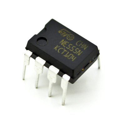
The NE555 is a robust and stable 8-pin integrated circuit that can be used as a very precise monostable, bistable, or astable multivibrator to produce a variety of applications such as one-shot or delay timers, pulse generation, lamp flashers, alarms and tone generation, logical clocks, frequency division and converters, etc.
It is a small circuit provided in an 8-pin DIL package. This circuit has great stability, allowing for the precise generation of pulses or rectangular signals. Its output power can reach 200 mA with a voltage of 15 volts. A time base can also be realized, with the duration determined by a capacitor and a resistor.
NE555 Features
- Supply Voltage: +16V
- Power Dissipation: 600mW
- Operating Temperature: 0°C to +70°C
- Soldering Temperature: 300°C (50s)
- Temperature Stability: 0.005% /°C
- Maximum Operating Frequency: 500kHz
- Compatibility: TTL
- Inertia: <2ms
NE 555 Pinout
- GND: Ground
- TRIG: Initiation of timing input. When TRIG < ½ CONT, it triggers the output high and opens the discharge.
- OUT: Timer Output Signal with High Current
- RESET: Active-low reset input forces the output and discharge to a low state.
- CONT: Adjusts comparator thresholds, produces Outputs at 2/3 VCC, and enables connection of a bypass capacitor.
- THRES: End of timing input. When THRES > CONT, it sets the output and discharge to a low state.
- DISCH: Output in open collector configuration for discharging the timing capacitor
- VCC: Input voltage range: 4.5 V to 16 V. (SE555 maximum is 18 V)
Applications
Pulse generator, time base, timer, siren…
NE 555 Pulse Generator
The frequency is obtained by the following formula:
F=1.46/((R1+2R2)´C)
Timer