I've been living in San Diego for three years now. I was born in the Pacific Northwest, home of the west coast's worst weather.
On Saturday I'm moving in to a new place and this will be the first time I've had a back yard in California. To celebrate the occasion, I'm thinking I need to build me something for listening outside. I have some JBL Control Nows that will cover everything from 100hz and up, but I need a sub.
The Bose Wave Cannon seemed like a solid choice for a few reasons:
1) It's easy to weatherproof. The woofer is buried inside the tube.
2) It's difficult to steal. I could build a tapped horn, but they're fairly easy to lug around. A Bose Wave Cannon is over TWELVE FEET long. Its hardly portable.
3) It's easy to build. Just go to Home Depot, get some Sonotube, bolt the driver in, D-U-N
4) It's cheap. You can build a Bose Wave Cannon for well under $100. A nice one can be built for $200.
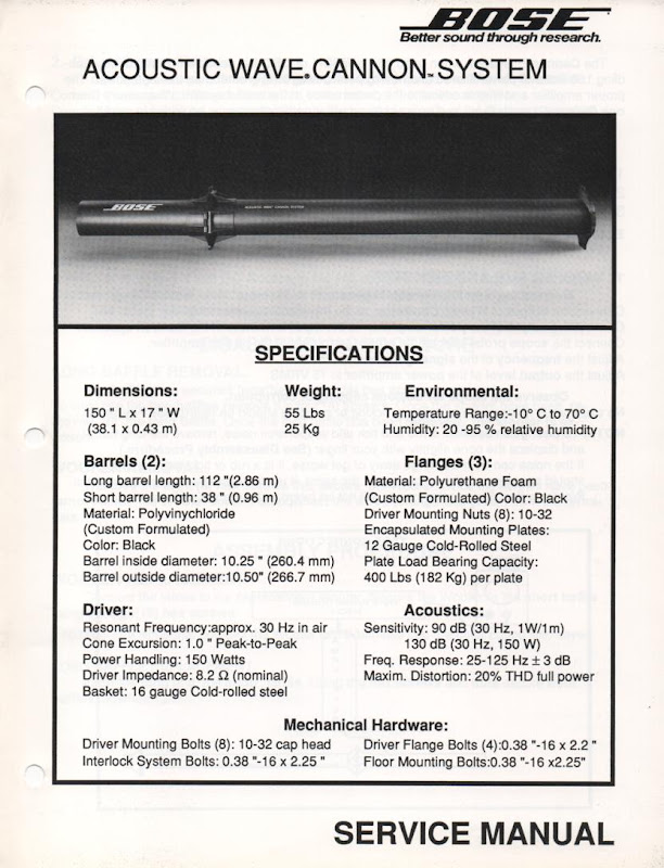
Here is the spec sheet.
On Saturday I'm moving in to a new place and this will be the first time I've had a back yard in California. To celebrate the occasion, I'm thinking I need to build me something for listening outside. I have some JBL Control Nows that will cover everything from 100hz and up, but I need a sub.
The Bose Wave Cannon seemed like a solid choice for a few reasons:
1) It's easy to weatherproof. The woofer is buried inside the tube.
2) It's difficult to steal. I could build a tapped horn, but they're fairly easy to lug around. A Bose Wave Cannon is over TWELVE FEET long. Its hardly portable.
3) It's easy to build. Just go to Home Depot, get some Sonotube, bolt the driver in, D-U-N
4) It's cheap. You can build a Bose Wave Cannon for well under $100. A nice one can be built for $200.
Here is the spec sheet.
The spec sheet says the Bose Wave Cannon is tuned to 30hz, and my sims in Hornresp confirm this.
With tapped horns, I frequently tune the horn to 0.707 times the drive resonance. For instance, if I have a driver with a free air resonance of 42hz, I tune the tapped horn to 30hz. (42.42hz * 0.707 = 30hz)
In the Bose Wave Cannon, I have to do the reverse, instead of tuning the horn to the driver, I have to find a driver that fits the horn.

The Eminence Kappa 12A seems to be a good candidate. It has the correct FS, it's inexpensive, it has fairly high BL (good for horns), and good power handling.
Here are the specs:
Product Specifications
Nominal Diameter : 12"
Power Handling (RMS)450 Watts
Sensitivity : 99.3 dB 1W/1m
Voice Coil Diameter : 3"
Magnet Weight : 80 oz.
Thiele-Small Parameters
Resonant Frequency (Fs) : 45 Hz
DC Resistance (Re) : 5.41 ohms
Voice Coil Inductance (Le) : 0.77 mH
Mechanical Q (Qms) : 7.76
Electromagnetic Q (Qes) : 0.28
Total Q (Qts) : 0.27
Compliance Equivalent Volume (Vas) : 3.96 ft.³
BL Product (BL)15.2 Tm
Maximum Linear Excursion (Xmax)3.2 mm
With tapped horns, I frequently tune the horn to 0.707 times the drive resonance. For instance, if I have a driver with a free air resonance of 42hz, I tune the tapped horn to 30hz. (42.42hz * 0.707 = 30hz)
In the Bose Wave Cannon, I have to do the reverse, instead of tuning the horn to the driver, I have to find a driver that fits the horn.
The Eminence Kappa 12A seems to be a good candidate. It has the correct FS, it's inexpensive, it has fairly high BL (good for horns), and good power handling.
Here are the specs:
Product Specifications
Nominal Diameter : 12"
Power Handling (RMS)450 Watts
Sensitivity : 99.3 dB 1W/1m
Voice Coil Diameter : 3"
Magnet Weight : 80 oz.
Thiele-Small Parameters
Resonant Frequency (Fs) : 45 Hz
DC Resistance (Re) : 5.41 ohms
Voice Coil Inductance (Le) : 0.77 mH
Mechanical Q (Qms) : 7.76
Electromagnetic Q (Qes) : 0.28
Total Q (Qts) : 0.27
Compliance Equivalent Volume (Vas) : 3.96 ft.³
BL Product (BL)15.2 Tm
Maximum Linear Excursion (Xmax)3.2 mm
This type of alignment does have some significant advantages but it also has some very significant problems. Whenever you have sound sources (two different tl terminuses) several feet apart (at each end of the tube) you will get a dramatically different frequency response depending on where the listener (or mic) is located in reference to the two sound sources. In the far field you might get something close to the Hornresp prediction when the path difference is zero, but in the near field, you could take your mic and walk around the sub and measure a different frequency response at each step.
Here's a post I made awhile ago showing the effect of playing with the Hornresp path length for a long (558 cm) end loaded tl. This shows the response at 3 different locations - first at one meter with both ends equidistant from mic (which is actually physically impossible unless the line is folded), second showing response at one meter from the terminus with the driver 6.58 meters away, and third the response at one meter from the driver with the terminus 6.58 meters away.
These three sims show that for a long sonotube tl you will get a dramatically different measured response as you walk around the sub - each step you take in a semicircle around the sub will give a different measured response. This is due to the two sound sources being located so far from each other, and it applies to wave cannons as well. This is why I don't really care for really long pipe designs.
First picture shows user inputs, schematic drawing, frequency response and excursion at 3000 watts with a 15 hz 4th order high pass. Xmax is 28 mm so it's a bit past but 3000 watts is a nice round number and a couple mm past xmax won't hurt. The 3000 watts might hurt thermally though, if it's a sustained sine wave type of signal.
An externally hosted image should be here but it was not working when we last tested it.
Now that is all fine and it's a decent approximation of what you might get in the far field if measured outside from a far distance. BUT as I said, the problem with these big pipes is that the sim assumes the driver and the port are coincident, like right next to each other (or more accurately that the driver and port are both equidistant and exactly 1m from the mic). Since this is NOT the case for a long tube sub (unless it's folded in half) anyone in close proximity will get a different frequency response depending on their relative position to the driver and the port.
For example here's two examples of the EXACT SAME SUB but with a different mic position. First, the mic (or listener) is sitting 1 meter away from the port exit and 6.58 meters from the driver. So the tube would be laid out on the ground and the listener would be sitting to one side of the sub with the port close and the driver far away.
In the second case the situation is reversed, the listener is sitting 1 meter from the driver and 6.58 meters away from the port.
As you can see if you put this thing on the ground and walked around it you would measure a different frequency response at each step (until you got halfway around, then the measurements would start to repeat the ones you measured in the first half circle).
If the sub was standing up in a corner and there was nobody anywhere near it (very far field audience), then the audience might get a more uniform coverage like the original (coincident) sim predicts. In that case the room will still have it's way with the response but the sub alone won't be responsible for gross differences in response determined by audience member individual location in relation to the port and driver.
An externally hosted image should be here but it was not working when we last tested it.
I agree, but I may fold it. These are easy to fold; you just put a wood divider right down the center, bringing the wavefront from one end within inches of the driver origin.
This could be particularly useful because modern subwoofers have low VAS
Another option would be to leave it *unfolded* and stuff it. That would turn it into something akin to a 'Tapped U-Frame.' You'd have the cardioid response of John Kreskovsky's U-Frame subwoofers, but it would be weatherproof. This could be particularly useful outside, to keep from bugging the neighbors. My new home has a canyon behind it, so I could fire The Hot End of The Cardioid into the canyon (and the backyard too.)
Last edited:
Folding it and having both sound sources side by side would indeed completely eliminate this issue.
I'm having a hard time picturing what you mean by a wood divider down the center to accomplish the fold (and still be able to fit the driver inside), but I'm sure you have something in mind, you are pretty creative.
I'm having a hard time picturing what you mean by a wood divider down the center to accomplish the fold (and still be able to fit the driver inside), but I'm sure you have something in mind, you are pretty creative.
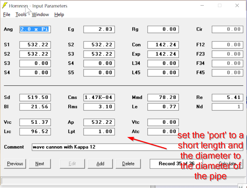
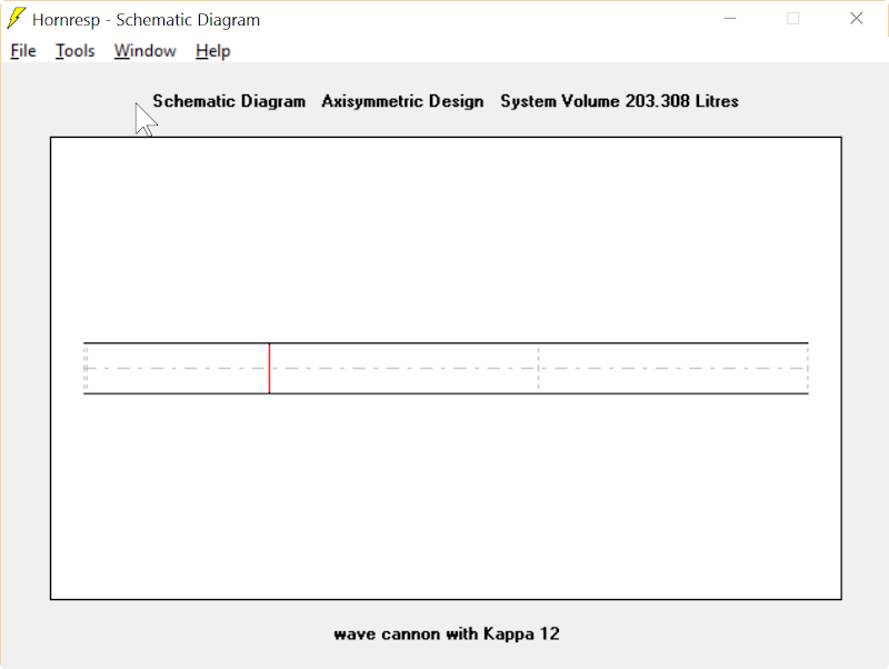

Here's a Hornresp model of the Bose Wave Cannon. This is a verbatim copy of the Bose design, using the Eminence Kappa 12A.
Some observations:
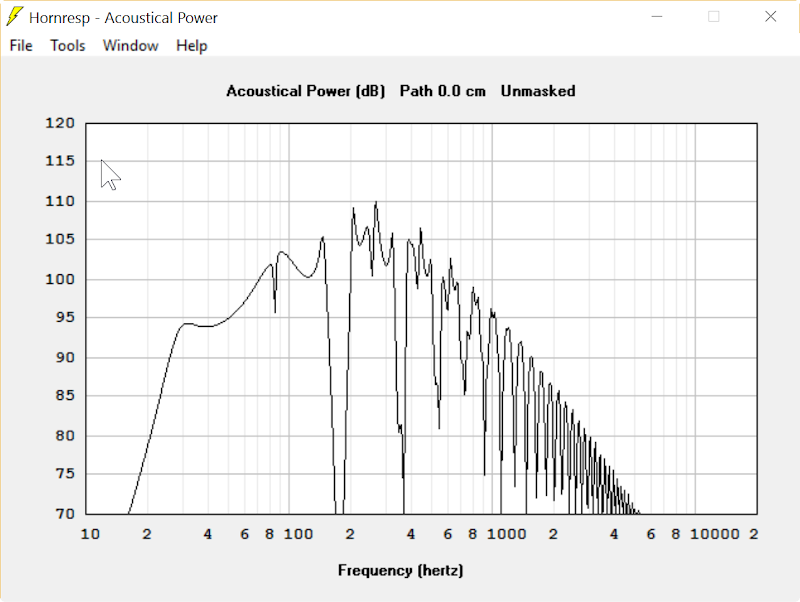
1) Sensitivity is quite good, which is nice outside
2) lots of high frequency hash, this one will need active filtering

The addition of a high pass and a low pass cleans up the response significantly. Now we have broad flat response, perfect for a subwoofer. Efficiency is still quite high.
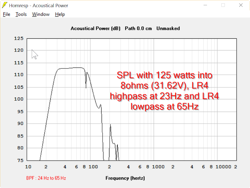
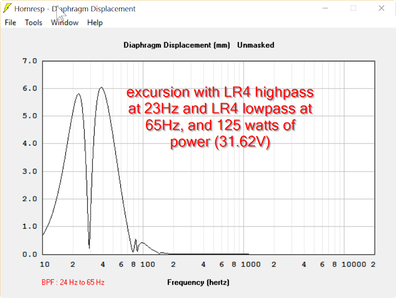
The limiting factor on the Bose design seems to be the excursion of the woofer. Bose advertises power handling of 150watts; I found that I couldn't exceed 125watts. That's not very good for a sub; I really need a driver with more displacement here. I have no idea where Bose came up with their maximum SPL figure of "130dB"; this design maxes out at 113dB. I'm guessing that Bose's figure is based on the high frequency hash that the sub produced above 150hz (which we want to filter out anyways.)
I find it a lot simpler and more straightforward to simulate a wave cannon as CH (compound horn) than the way you did it here.
Who knows what Bose' max spl was based on. Maybe in room response including 15 db room modes. Regardless, everybody lies on their spec sheets, you can safely completely disregard EVERYBODY'S max spl spec and assume it's a figure made up by the marketing dept, not the engineering dept.
Who knows what Bose' max spl was based on. Maybe in room response including 15 db room modes. Regardless, everybody lies on their spec sheets, you can safely completely disregard EVERYBODY'S max spl spec and assume it's a figure made up by the marketing dept, not the engineering dept.
Example of Hornresp inputs for a (really bad) wave cannon design simulated as CH. This also includes a "bump" in the line for a driver loading chamber, the guy wanted to use a wood box to load the driver and have his pipes sticking out on either end of the wood box. It's easy enough to remove this wood box driver loading "bump" if desired, the main thing is to show it's easier to simulate the wave cannon as CH.
An externally hosted image should be here but it was not working when we last tested it.
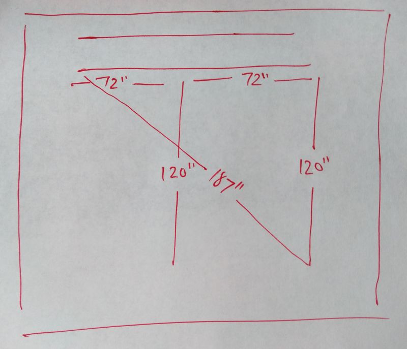
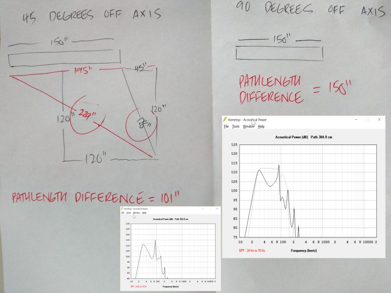
If I'm not mistaken, hornresp can't do polar response sims for compound horns. But we can do it by hand, using plain ol' Pythagorean theorem.
Here's an analysis of the Bose Wave Cannon from two points. The first point is immediately in front of the cannon, with both ends of the cannon equidistant.
The second point is from the *right* end of the cannon, so you're 67" further from one end of the cannon than the other end.
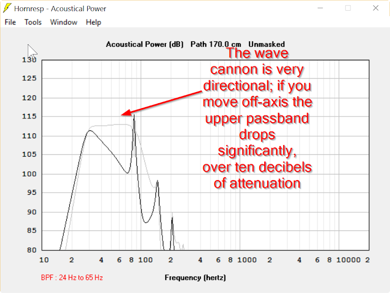
In the sim, you can see that the cannon is *very* directional. Nearly twelve dB of attenuation when you move off-axis.
This is pretty neat, particularly if you're outside with neighbors to the left and right, but no one behind you.
The reason that the wave cannon is directional is because of path length differences. For instance, 80hz is fourteen feet long. This mean that if you reach a point where the pathlength from one side of the cannon is 14', and the pathlength to the other side of the cannon is 21', the output of the two sides will cancel each other 100%.
Naturally, you won't get perfect cancellation in the real world.
But if you understand how the pathlengths work, you'll see that a regular horn won't do this weird trick, because there's only one mouth. The directivity of the Bose Wave Cannon is due to the dual mouths, and the pathlength differences between them.
Due to the wonders of Hornresp, it also looks like you could optimize the design. Here's how you'd do it:
1) Decide how you want to orient the cannon. Do you want it mounted left to right? Up and down? Front to back? Make that decision first.
2) Decide where you'll be listening. Are you listening at a distance of 10'? 20'? 5'?
Once you have those numbers, juggle the length of the front horn and the back horn for flattest response on axis. The off-axis response will then be attenuated, because the off axis response will not be in-phase.
The trick here is to avoid the *other* possibility, which is that the ON axis response is out-of-phase, and the off-axis response is IN-phase. That would be a worst case scenario, where the cannon is 'throwing' lots of bass where you don't want it.
Another possibility there would be to do it intentionally. For instance, if you lived in a two-story apartment you could put The Hot Side of The Cannon into the ceiling, to spare your neighbor downstairs.
The trick here is understanding where The Hot Side of The Cannon is aimed. Based on an hour worth of sims, the Hot Side *isn't* the mouth of the cannon, it's the side. (But again, you can change this if you want to, particularly with modern tools like HornResp. The Bose Wave Cannon is over twenty years old, and back in the nineties even companies like Bose didn't have anything close to HornResp. Sophisticated analysis of transmission lines has only been possible for about ten years.)
I ran some more sims at various angles.
This is a weird beast, because you can't easily design it so that the null is at a specific frequency. (In the last post, I was thinking that would be possible.)
IE, if you were trying to design the wave cannon so that it had an off-axis null at 80hz, it can't be easily done, because the frequency of the null is dependent on both distance and angle.
The illustration above illustrates that the frequency of the null is higher in frequency at 45hz, and it's very deep. At 90 degrees off-axis the null is not as deep, and it is lower in frequency.
The obvious answer is to fold the cannon. The directivity of the Wave Cannon is due to the pathlength difference from one mouth to the other; therefore you can reduce the directivity by reducing the pathlength difference.
But I *like* the directivity! To me, that's not a defect that's a feature. Ten decibels of attenuation at 80hz is a LOT. That means that I can listen on-axis at 100dB, while my neighbors are only getting 90dB. I like that.
It could also be handy for a home setup, where you could reduce reflections off the sidewall. The Wave Cannon isn't as directional as a dipole but it's a heck of a lot more efficient.
To me, the best solution for the frequency response would be to EQ it to a flat power response. Basically walk around the room, measure what the SPL looks like in a few different locations, then set the EQ and the crossover accordingly.
This is basically what I showed in post 3, wildly different frequency response depending on the triangulated location of the mic vs the two sound sources. Hornresp has no problem showing the frequency response at any given location as long as one of the sound sources is located 1m from the mic.
As long as the audience position is somewhat fixed and somewhat nearfield, this could be used as a crude directivity control.
Now I'm not good at math but it would seem that in the far field this would break down to some extent. For example, if your tube length is 120 inches (leg a) and your distance from the right angle is 1 inch (leg b) then the ratio of leg a to leg b is 120:1, in other words you are in the extreme nearfield of one end of the pipe and FAR off axis (if the axis is perpendicular to the middle of the pipe as Hornresp assumes with zero path length sims).
But if leg b is increased to 12000 inches you are now in the farfield of both ends of the pipe and the ratio of leg a to leg b is very nearly 1:1, in other words almost directly on axis.
I'm not nearly good enough at math to figure out how this applies to a full polar map at all angles and distances and frequencies but it would seem that in the farfield this directivity control would be somewhat limited.
Also, in a small room this directivity control might not apply at all since you have waves bouncing all over the place - you have several extremely nearfield solid reflection points, not a unified unobstructed wave propagation.
Worst case scenario would be if this was in your backyard and the audience was all in the nearfield and all surrounding the pipe - sitting around it like a campfire. Everyone would be getting dramatically different frequency response and in the farfield I think the frequency response would be relatively uniform - in other words bad for everyone in the nearfield and not much attenuation for the neighbours.
As long as the audience position is somewhat fixed and somewhat nearfield, this could be used as a crude directivity control.
Now I'm not good at math but it would seem that in the far field this would break down to some extent. For example, if your tube length is 120 inches (leg a) and your distance from the right angle is 1 inch (leg b) then the ratio of leg a to leg b is 120:1, in other words you are in the extreme nearfield of one end of the pipe and FAR off axis (if the axis is perpendicular to the middle of the pipe as Hornresp assumes with zero path length sims).
But if leg b is increased to 12000 inches you are now in the farfield of both ends of the pipe and the ratio of leg a to leg b is very nearly 1:1, in other words almost directly on axis.
An externally hosted image should be here but it was not working when we last tested it.
I'm not nearly good enough at math to figure out how this applies to a full polar map at all angles and distances and frequencies but it would seem that in the farfield this directivity control would be somewhat limited.
Also, in a small room this directivity control might not apply at all since you have waves bouncing all over the place - you have several extremely nearfield solid reflection points, not a unified unobstructed wave propagation.
Worst case scenario would be if this was in your backyard and the audience was all in the nearfield and all surrounding the pipe - sitting around it like a campfire. Everyone would be getting dramatically different frequency response and in the farfield I think the frequency response would be relatively uniform - in other words bad for everyone in the nearfield and not much attenuation for the neighbours.
Last edited:
(But again, you can change this if you want to, particularly with modern tools like HornResp. The Bose Wave Cannon is over twenty years old, and back in the nineties even companies like Bose didn't have anything close to HornResp. Sophisticated analysis of transmission lines has only been possible for about ten years.)
To address this part specifically, Akabak is 20 years old this year and it can do almost everything Hornresp can and a few things Hornresp can't. The tech was there LONG ago, not sure if BOSE was using it or not.
Try a sim with the pipe folded so the ends are 1/2 the total length apart.
(see half-square antenna theory)
Just tried that, the response wasn't a whole lot different than the Bose Wave Cannon
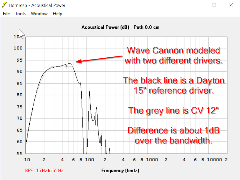
Here's something strange about this enclosure, it's *insanely* insensitive to what driver you use. The pipe dominates the response shape. The graph above shows the exact same Wave Cannon, one modeled with a Cerwin Vega 12", and one with a Dayton Reference 15" woofer. Major differences in qts, vas, and SD. Doesn't seem to make much of a difference.
... The trick here is understanding where The Hot Side of The Cannon is aimed. Based on an hour worth of sims, the Hot Side *isn't* the mouth of the cannon, it's the side. ...
They were supposed to be mounted horizontally on the front wall of the theatre behind the screen. When more than one was used, they were stacked one above the other.
I remember the demonstrations back in the 90's and they where meant for installs in cinemas, I also remember an install in a club in Rotterdam, 4 of the AWCSII types and also in a cinema in Belgium where they had 6-8 of them, not know what version it was.
I don't think the 3mm of the Alpha is enough, seeing the original woofer
I don't think the 3mm of the Alpha is enough, seeing the original woofer
Last edited:
Deep Throat
The attached drawing [1] shows my preliminary design for a similar device, except it is single ended and designed for use with an 18" long-throw driver. It is to be fabricated from standard, heavy-walled SonoTube. I have not run simulations yet to tweak the design. Design information is contained in the attached spreadsheet [2].
Regards,
WHG
Attachments
- Status
- This old topic is closed. If you want to reopen this topic, contact a moderator using the "Report Post" button.
- Home
- Loudspeakers
- Subwoofers
- Bose Wave Cannon