Sorry I’m really busy at work and I couldn’t work on the piece… Anyway you are right! I didn’t notice that rotation in the middle.
The process is the same that @DanielPiker suggested. To make the rounded and more precise shape I used the kangaroo component that pull points to the curve. So I was able to keep the shape close to the drawing.
I was thinking in those days that it’s maybe necessary to separete the mirrored shapes in the middle so to create a little gap and close this with a new mesh. The crease in those case won’t be created!
I didn’t try it but I think in this way, that in theory should work, I could have the problem when I will join everything together because I won’t have the naked vertices in the same position to join… It’s hard to explain I will show the problem when I can work on the model
If you are using Meshmachine to refine your mesh then try using the FixV input to fix the vertices on the naked edge and make sure these are already in the right positions so that they match the rotated shape.
Still not quite got it really smooth and it’s not quite a closed mesh (although repairs easily in Netfabb) but this is minimal surface through the holes and then pulled out to an arc to get it round…
Nearly there (again, still)… I just need a mesh expert, possibly some C#, to stitch up the seams in the meshes using GH instead of having to do the last bit manually…
This leaves a gap around the edges which is filleted in the original sculpture. I can fill this gap in manually (and tediously) but does anyone know how I could do this in GH? Meshes attached, internalised in GH file. STITCH_MESH_GAPS.gh (27.1 KB)
Looks (and feels) great in oak!
I’m getting one hard to machine area right in the centre twist which might be to do with setting Z heights after flipping the block over to machine the back face. Still have a lot of trimming and sanding to do.
There is one last thing about the shape that I can’t figure out… the original looks like it is convex at the top and bottom - it is minimal through the holes but blends to convex as these surfaces meet the edge of the shape - whereas using a mesh relaxation / minimal surface this area will be slightly concave.
The ubiquitous yin-yang symbol holds its roots in Taoism/Daoism, a Chinese religion and philosophy. The yin, the dark swirl, is associated with shadows, femininity, and the trough of a wave; the yang, the light swirl, represents brightness, passion and growth. John Bellaimey explains why we all contain the spirit of yin and of yang – and how we can achieve a balance of both in our lives.
I hope I am not intruding on this topic. The overall description (Minimal Surfaces) is certainly fitting but the specific forms under discussion are different than my current challenge.
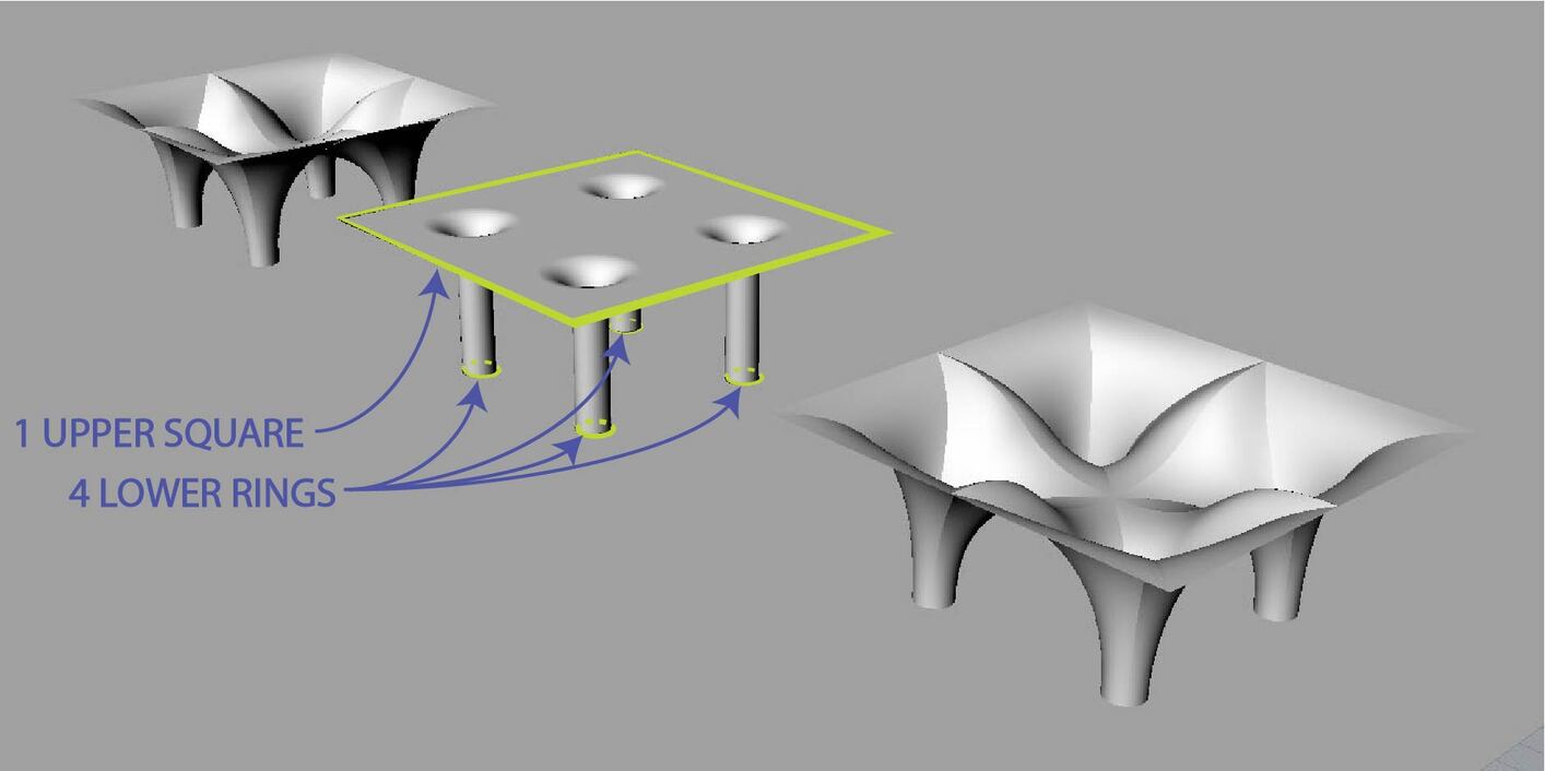
I’ve been struggling to generate a smooth shape that is defined by five border conditions: One large square and four smaller circles:
A careful inspection of this image will reveal that I had difficulty avoiding the selection of multiple nodes at once and this complicated what should have been a simple selection of perimeter elements.
All this to say that the mesh that I have been using as a basis for “relaxation” is not behaving as I would like. The existence of edges inside the mesh appear to also be derailing the proper execution of this script:
I have also seen a few tutorials online using the Kangaroo Physics Modelling Grasshopper plug-in by Daniel Piker and I’m wondering if this might be a better approach to achieving the desired result. The tensile structure video examples are pretty amazing. Any help on Grasshopper case studies that might relate to this specific application are greatly appreciated.
are you aware of the Sub-D surfaces introduced in Rhino 7? The main issue with direct modelling was always the continuity when modelling such shapes from surfaces. Only an experienced modeler could actually create good shapes out it. Of course there are automated approaches by using Kangaroo or other scripts to yield minimal surface meshes. But are you really in need to create perfect minimal surfaces? The issue with calculated approaches is always the missing freedom in design. I would rather use Sub-D surface modelling and check the curvature analysis for mean curvature converging to 0 (or at least reducing extremes in positive or negative direction).
Hi Tom. Wow. I just watched an introduction to Sub-D. That is going to be a game changer. I have spent embarassing hours working on repairing edges, patching holes and creating good curves for curve networks for the Network Surface command. Having said all that… the ability to create minimal surfaces would still be quite useful for many of my architectural modelling applications…but Rhino 7 is definitely something I would like to try sometime soon. Do you think Kangaroo would have much trouble modeling a minimal surface between the five surfaces I’m showing? Thank you for the help.
The initial mesh you choose can have a huge effect. If you can find the time to follow this topic you can see we start with an initial mesh and then subdivide it before the minimal surface bit happens.
MeshMachine by @DanielPiker is a great tool for this.
You can start with a basic mesh and define fixed vertices and boundary curves and MeshMachine will give you a nice mesh which will then relax to a nice shape.
Something to bear in mind here is that for the curves you show, the only true minimal surface (zero mean curvature) possible is 5 flat patches!
Because it is defined by a balance between the principal curvatures at each point (they have to be equal and opposite), a minimal surface can never form long thin necks like this.
I’m guessing though that what you are actually after is a relaxed surface, as could be formed by a fabric with all parts in tension (just not equal tension in all directions).
Kangaroo can find both true minimal surfaces and more general relaxed surfaces, and it would be fairly simple to set up here.
It’s true as martyn says that the initial mesh is key.
I would actually use a regular quad mesh for this case though - it’s probably easier to control.
This just looks tremendously helpful.Thank you Daniel. I’ve been looking at Shigeru Ban’s Pompidou Center in Paris and taken by the lattice structures he has been able to achieve.
The distance between something that is actually “structurally expressive” and what “looks good” is often deceptively far apart but I thought I would start at least looking at methodologies for replicating these smooth surfaces with wood latticework as a starting point.
Your illustration is right on the dot. I’ll download this grasshopper file and see how far I get. I did manage to get Kangaroo 2 installed.
Interesting what you say about the four circles being the minimal surface. I think I read some information previously in this thread about “necking” and it sounds like that phenomenon is what you are discussing. Among other things, a piece of fabric has the ability to deform as a function of its length in a given direction. I suppose soap film doesn’t perform the same way.
Thank you again for all this. You have me wanting to recall my primitive, and somewhat bygone, understanding of eigen values, gaussian curvature, mean curvature and such…The Kangaroo engine is great and I can’t wait to introduce it to my son who is in the middle of a high school physics class.
No Kangaroo as physics engine is a great tool for relaxing shapes just as Daniel has shown here. Yet the outcome is a dense mesh. This works great and extremly easy if you have no modification in mind later on.
But just imagine you want to cut out a specific part of it. Now you are dealing with meshes and this becomes really difficult to do. Especially if your cutout shape is curved.
I mean you can combine both approaches. Create a mesh as reference and reverse it with Sub-D surfaces. Sub-D can be easily converted to Nurbssurfaces.
Of course the surface layout is not optimal, but its curvature continious and the eye doesn’t stop somewhere.
My point is just, if you don’t care about having a perfect relaxing shape, you can directly go for sub-d and give your form a unique detail.
“Mean curvature” is just that both principal curvatures (at u and v direction, which are directed/signed) sum up. Its “Minimal” if they sum up to be close to 0. This basically reduces the tension of a shape and makes it “relaxed”. Rhino has analysis tools for that. So a pure modelling approach can be optimized by having this analysis on.
If one implements structured quadrilateral meshes (i.e. where the order of the vertices within each subdivided coarse face is a regular grid going from left-to-right/down-to-up) it’s pretty trivial to convert the relaxed mesh into NURBS patches after the form finding stage. Here’s an old example of this workflow (about 20 seconds in):
Edit: Since this was originally part of my PhD studies I think I can share it. Here’s the subdivision and mapping components I wrote implemented into Daniel’s example above (baked brep on the right). Note that the NURBS patches don’t have great continuity with this method, but I imagine that could be implemented as well (maybe even using K2 goals):
If it has to be a minimal surface, then once the boundary is set, the shape is determined, and isn’t something you can change. For certain boundaries there might be a small number of discrete options to choose between, but that’s it.
If the target is just something with a smooth looking shape that’s going to be built out of rigid material, and you want lots of freedom in the shape, then I agree, hand sculpting a SubD might be easier.
If it’s going to be an actual tensile structure though, the possible shapes are still strongly constrained if you don’t want your fabric to end up flappy or wrinkly.
While it doesn’t have to be a minimal surface, as the tensions in warp and weft directions can be unequal, you do need them to be physically consistent across the surface. Sculpting something which does this by hand seems rather tricky, as you wouldn’t have any feedback about the balance of forces. Yes, you can check the mean curvature, but since there are valid tensile shapes far from minimal, it won’t be much help there.
Also, one correction - the 2 principal curvatures are not generally in the u and v directions of a parametric surface - they follow their own set of directions and are always perpendicular to each other. This interplay between the directions of geodesics, principal curvatures, and the actual warp/weft fibers of the fabric is one of the most complex parts of designing layouts and cutting patterns for tensile structures.
Thanks for sharing these!
Great to have some better ways of generating the strips.
Also, interesting point about continuity of NURBS surfaces.
Here’s some nice work on relaxing NURBS directly in Kangaroo with some isogeometric goals:
The same group have also developed a whole plugin around isogeometric analysis - Kiwi3d.
I wonder as well if with the native Rhino SubD objects now, whether it might make sense to create some specifically SubD based goals. Of course one can already relax the control mesh of a SubD and have it update, but interesting to think about basing the forces not on the edges of the cage, but the changing surface of the SubD patches themselves.